CSI Bridge 26.1.0 Build 2968 Win x64

Free Download CSI Bridge 26.1.0 (2968) | 902.9 mb
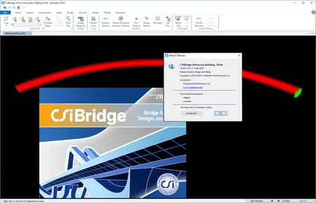
Computers and Structures, Inc. (CSI)is pleased to announce the availability ofCSiBridge 26.1.0 (2968)is specialized analysis and design software tailored for the engineering of bridge systems
Owner:Computers and Structures, Inc. (CSI)
Product Name:CSiBridge
Version:26.1.0 (2968) Advanced with Rating
Supported Architectures:x64
Website Home Page :www.csiamerica.com
Languages Supported:english
System Requirements:Windows *
Size:902.9 mb
CSiBridge v26.1.0 Enhancements – Date: 25-Oct-2024
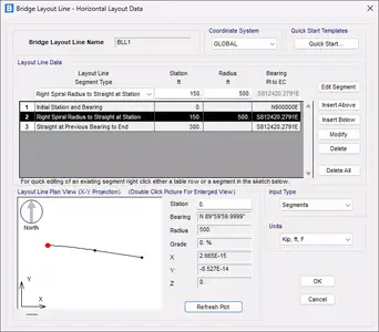
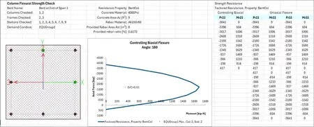
CSiBridge v26.1.0 expands the layout line to support highway curves with unequal spirals or individual spiral segments. In addition, comprehensive calculation reports for Eurocode substructure column strength checks are now available.
Bridge Modeler
Bridge layout lines can now include a highway curve with unequal spirals or individual spiral segments.

Bridge Design and Rating
Comprehensive calculation reports for Eurocode substructure column strength checks are now available.

Below lists changes made to CSiBridge since v26.0.0, released 05-September-2024. Items marked with an asterisk (*) in the first column are more significant
* 10795An enhancement was implemented to add comprehensive calculation reports for Eurocode substructure column strength checks.
* 9341An enhancement has been implemented, adding four new spiral segment types to the bridge layout line definition. The new segment types are: ‘Straight to Right Spiral Radius at Station’, ‘Straight to Left Spiral Radius at Station’, ‘Right Spiral Radius to Straight at Station’, and ‘Left Spiral Radius to Straight at Station’. The bearing of the end station is calculated based on the spiral length and the radius. These four new spiral segment types allow definition of a non-symmetric highway curve, i.e., the entering transitional spiral curve length can be different from the exiting transitional spiral curve. In addition, whenever the end bearing of any segment is changed, the end bearings of all subsequent segments are automatically updated by the same change in angle until a ‘Straight at New Bearing’ segment is encountered, if any. This includes the Circle Right/Left by Radius segments, which may cause a change in end bearing angle for the segment. When working with PI to PI data, any set of three points that define a perfect circle with no straight segments and no spirals will be converted to a segment of type Circle Right/Left to New Bearing at Station.
* 10833The version number has been changed to 26.1.0 for a new intermediate release.
10817An incident has been resolved for steel I- and U-girder bridge design and rating in which the program would fail to design/rate the bridge if the steel girders were nonprismatic and the assigned parametric variation of a span was such that one of the control distances was within 2 inches of the span end. When this occurred, adjusting the problematic parametric variation control distance to be further from the end would allow the design/rating to complete.
10821An incident has been resolved for Eurocode steel bridge design checks in which the program incorrectly used an opposite assignment of the design parameter End Post Type (available options were Rigid, and Non-rigid End Post) for design. The design results could be slightly affected due to this error.
10842An incident has been resolved for steel I-girder bridge design/rating in which the bottom flange unbraced length may not have been calculated correctly during the design process when two or more staggered diaphragms were assigned at the same skewed global section cut location in different girder spacings.
10964An incident has been resolved for steel U-girder bridge design in which the design and rating results could be affected when there were longitudinal stiffeners assigned to the steel U- girders. The error was due to double counting the stiffeners when evaluating the elastic section properties of the section. Plastic section properties were not impacted.
10791An incident has been resolved for steel I/U-girder and concrete I-girder bridge section load generation in which the bridge section loads – SIP (stay-in-place form) load (only for steel I- girder bridge sections), haunch loads, and construction temporary load with non-zero additional overhang load were generated incorrectly in the following two situations: (1) For steel I-girder bridges, the girders were nonprismatic hybrid I-sections and some of the bridge section cuts containing zero haunch height at some (not all) of the girder locations. In other words, all girders were different nonprismatic hybrid I-sections. (2) For steel I/U-girder and concrete I-girder bridge sections, when the layout line within a span was curved to the left and the girder longitudinal layout was set as Straight Line, the bridge section loads mentioned were generated parallel to the layout line instead of the straight girder line.
10801An incident has been resolved in the Segmental Bridge Erection Sequence Schedule Wizard in which the wizard incorrectly generated traveler movements onto non-existing segments when uneven cantilevers were assigned to the segmental bridge.
10818An incident has been resolved for bridge tendon geometry in models with at least six bridge objects and the first bridge object contained bridge tendons with complicated user-specified parabolic segments, when updating all bridge objects, the tendons in the first bridge object could be incorrectly changed into straight tendons. This was a very rare case and did not always happen.
10851An incident was resolved in the bridge modeler where the bridge object geometry could have been incorrect when parametric variations were defined for the entire length of the bridge and assigned to the bridge section insertion point location with the distancemeasured from the start abutment. This issue was uncommon and depended on the distances specified in the parametric variation definition.
10886An incident has been resolved for modeling precast concrete box girder bridges in which the girder geometry would be incorrectly generated at the beginning of each span and the bearing links could be disconnected from the bottom of the girder if the depth or top flange thickness of all girders were not the same.
10951An incident has been resolved for modeling a voided slab bridge in which a parametric variation applied to the void radius was using the value at the beginning of the variation definition along the entire length to which the variation was applied, resulting in the void radius being constant and not changing according to the variation definition.
10877An incident has been resolved for the concrete shell design according to ACI 350-20 and Eurocode 2-2004. For the ACI 350-20, the overwrites of the environmental durability factors for axial force, moments, and shear forces were always taken as unity. In addition, the Consider Environmental Durability Factor in the preferences was always considered in design. Now, the environmental durability factors will be taken from the overwrites but will not be considered if the load combo is seismic or wind and ‘No’ is selected for the Consider Environmental Durability Factor in the preferences. For the Eurocode 2-2004, the ratio of the principal shear demand over the concrete shear capacity is now calculated correctly.
10845An incident has been resolved for steel U-girder bridge concrete pour analysis in which the slab wet concrete overhang bracket loads on the exterior girders were not generated if longitudinal stiffeners were assigned to the exterior girder webs.
10844An incident has been resolved for AASHTO bridge substructure design in which the substructure design report was unable to be generated after design was performed. This was a reporting issue only and did not affect the design results.
10860An incident was resolved in section designer where the moment curvature output generated by the Details button on the Moment Curvature form would not display. This was a display issue only and did not affect results.
* 10883An incident has been resolved for the calculation of the beam/girder section cut forces and stresses of the precast concrete box girder bridge. This was a post-processing error and affected the Descriptions in the Bridge Response Display form, as well as the bridge design results.
10890An incident has been resolved for Descriptionting the girder responses in the Bridge Response Display form when there was more than one bridge object in the model. When this happened, the responses for the first bridge object remained correct. The girder responses for the remaining bridge objects were incorrect except when the girder number was the same as the bridge object number. This was a display issue and did not affect the design/rating results.
10895An incident has been resolved in the bridge response display form in which the program failed to display the 10th point displacement Description when a double bearing bent with non-zero Distance to End of Girder at the after bent connection was assigned to the start abutment of the bridge. This was a display issue and did not affect the analysis or design/rating results.
10933An incident has been resolved in section designer where the line bar editor beginning and end coordinates were not saved and displayed correctly after being changed.
19770An incident was resolved to only expose the ‘Other’ resistance option on the Bridge Design Request – Substructure form for bents whose columns do not have identical frame sections. The following additional checks were implemented: (1) When changing the frame section of bent columns, a warning will be issued if the bent is used in any substructure design request with the ‘Current’ resistance option, and the bent originally had all columns with the same frame section property, but the updated column frame section properties are not identical. (2) A warning will be issued when the user attempts to delete any frame section property that is used as a resistance section for the ‘Other’ resistance option. (3) If a bent location in a station range on the Bridge Design Request – Substructure form is changed such that the original bent location has columns with identical frame sections and ‘Current’ resistance option, and the new bent location has columns with different frame sections, the resistance option is set to ‘Other’, and the resistance section is set to the frame section assigned to the first column of the bent.
10792An incident was resolved to correct a minor issue with program-generated bridge groups for bridge spans. When a span name was changed, the previous program-generated bridge group for that span was not deleted automatically and was not allowed to be deleted by the user, which was unexpected.

CSiBridgeis specialized analysis and design software tailored for the engineering of bridge systems. Suspension, cable-stay, elevated-roadway, and other types of bridge systems may be modeled and designed to suit any one of a variety of purposes, including means for crossing water, linking points between shear terrain, or extending over highway infrastructure. Customized controls and features integrate across a powerful object-based modeling environment to offer an intuitive, practical, and productive computational tool for bridge engineering. Advanced modeling features and sophisticated analysis techniques account for dynamic effects, inelastic behavior, and geometric nonlinearity. Code-based templates streamline the engineering process from model definition through analysis, design optimization, and the generation of comprehensive output reports. CSiBridge is the premier software for bridge engineering.
Completely integrated within the CSiBridge design package is the power of theSAPFireanalysis engine, including staged construction, creep and shrinkage analysis, cable tensioning to target forces, camber and shape finding, geometric nonlinearity (P-delta and large displacements), material nonlinearity (superstructure, bearings, substructure and soil supports), buckling and static and dynamic analysis. All of these apply to a single comprehensive model. In addition, AASHTO LRFD design is included with automated load combinations, superstructure design and the latest seismic design.
CSiBridge’s Watch & learns
Founded in 1975,Computers and Structures, Inc. (CSI)is recognized globally as the pioneering leader in software tools for structural and earthquake engineering. Software from CSI is used by thousands of engineering firms in over 160 countries for the design of major projects, including the Taipei 101 Tower in Taiwan, One World Trade Center in New York, the 2008 Olympics Birds Nest Stadium in Beijing and the cable-stayed Centenario Bridge over the Panama Canal. CSI’s software is backed by more than three decades of research and development, making it the trusted choice of sophisticated design professionals everywhere.
DONWLOAD FROM RAPIDGATOR
http://peeplink.in/1e4d9b487fc1
TakeFile
jbbtx.CSI.Bridge.26.1.0.2968.rar.html
Fikper
jbbtx.CSI.Bridge.26.1.0.2968.rar.html
